Mobile Inverted Pendulum
This page summarizes experimental environments used for a variety of experiments and bases of control algorithm for stabilization of the robot.
Mobile Inverted Pendulum
As an actuator, a motor is attached to the bottom part of the body, and it drives the right and left wheels. Encorders attached to the wheel and a gyro sensor to the body respectively measure the rotation angle of the wheel and angular speed of the body. By using these information appropriately, we can maintain inversion of the robot and lead the robot to arbitrary position while maintaining inversion. A CPU board (H8 micro computer), motor driver and CPLD (Complex Programmable Logic Device) board are attached to the body. Any control algorithm is implemented by embeding a C program to the CPU board.
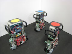 Mobile Inverted Pendulum Robot (ZMP: e-nuvo WHEEL) |
Basic Motion |
The above experimental environment is insufficient to perform various experiments on cooperative control and robotic networks. We thus build some additional setups listed below.
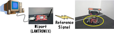
Experimental System 1 (Transmission of Command via Wireless Communication)
We first built a system to transmit the command of wheel angular velocity from PC to each robot via wireless communication, where we employ a wireless communication device Wiport(LANTRONIX). The tranmitted signal is received by the Wiport attached to each robot and sent to the CPU board via serial communication. Then, it is inputted to the embedded stabilizing controller as a reference signal. Here, because we use the UDP/IP protocol, it is possible to send messages to multiple robots simultaneously.
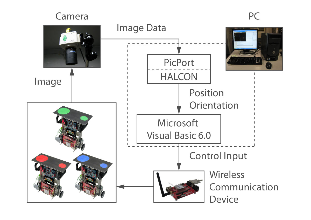
A MTV-7310 camera mounted above the robots has a resolution of 470 £ 570. The video signals are available in real time via a frame grabber board PicPort-Stereo-HrD and image processing software HALCON. The sampling period of the controller and the frame rate provided by the camera are 0.33[ms] and 30 [fps], respectively. The position and orientation of the robots are calculated by using the image processing. Based on these information, the PC computes desirable control input and sent it to robots.
The total system is illustrated by the following figure.
Experimental System 2 (Information Acquisition by An Onboard Camera)
In Experimental System 1, image information gathering and command inputs computation are performed by a PC. However, it is essential in cooperative control that each robot autonomously determines its motion based on the available local information. We thus built the following experimental system where an onboard camera is attached to each robot and robots move according to the visual information.
|
Control via Information from An Onboard Camera |
We attach the miniature camera RC-12/Morse type S (RF System) to each robot and the image data is transmitted to the image processing board PICOLO Diligent(EURESYS) attached to the PC. The remaining part is the same as Experimental System 1.
The total system is illustrated by the following figure.
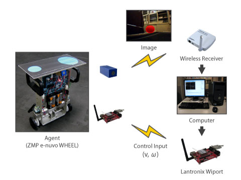
The image processing board can import four different data simultaneously and is applicable to experiments with multiple robots.
Experimental System 3 (Mixed Human-Robot Team)
We built an experimental system where a human navigates multiple robots. We use Wii remote (Nintendo) as an interface with the human.
Information from the acceleration sensor embedded with the Wii remote is transmitted to the Bluetooth USB adapter USB-DO-BT/CL attached to the PC. The PC computes the orientation of the remote controller based on the sensor data and sends a velocity command input according to the orientation to each robot via Wiport (LANTRONIX).
|
Operation with Wii Remote |
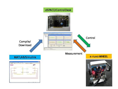
Experimental System 4 (Control with MATLAB/Simulink)
We built an experimental system with the disital signal processor DS1104 (DSPACE). This system is mainly used for education.
|
Stabilization of Pendulum |
Experiment 1 (H_inf Control of Inverted Pendulum)
|
Experimental Result |
Experiment 2 (Stabilization of Mobile Inverted Pendulum via Partial Feedback Linearization)
|
Experimental Result |
Experiment 3 (Inversion at A Slope)
|
Experimental Result |